

Understanding Layer 4 Aggregation and Filtering in Network Visibility
Introduction to Layer 4 Aggregation and Filtering
In modern high-speed networks, it’s not often feasible to monitor all traffic due to the high bandwidth. Tapping links and analysing every packet can overwhelm monitoring tools and increase costs. Aggregation and filtering provide an effective way to optimise visibility, reduce tool load, and maintain accurate monitoring coverage.
In passive visibility architectures, TAPs (Test Access Points) copy traffic from critical network links and Network Packet brokers aggregate and filter the traffic before it’s sent to tools. With this setup, TAPs ensure no packets are missed. Packet brokers forward packets relevant to the analytics tools, and the bandwidth requirement of the tools is reduced. It enables lawful interception, compliance monitoring, threat detection, and more.
What is Aggregation?
Aggregation is commonly used in networking. Aggregation can refer to several different scenarios.
Link aggregation or NIC bonding treats multiple links as a single logical link with various options such as load balancing or fault tolerance. Often, the term Link Aggregation Group (LAG) is used to define the bundling of interfaces.
On the receiving end, it is typical to receive packets from a high number of links or Spanned ports. Usually, the input links are utilising only a portion of the available bandwidth. Especially when the link utilisation is low (10-40%), a lot of output links can be saved if input links are aggregated together. While this can be beneficial in reducing the number of output links, careful consideration is needed to define the aggregation factor, taking into account microbursts.
For example, if there are two input links with an average of 50% link utilisation, aggregating them to one link has a risk of oversubscription since both links may experience peak traffic. Oversubscription means that the output link would have more bandwidth than it can carry.
Aggregation can be performed in various configurations, such as many-to-one, many-to-many, or one-to-many. In certain use cases, the term traffic forwarding may more accurately describe the process than aggregation.
Let’s focus on an example where we have four 25G inputs and the monitoring tool has a 100G input. In this case, we aggregate all the inputs and send them to one 100G output.

The benefits of aggregation or traffic forwarding include a reduction of the number of monitoring ports required and the ability to send traffic to several tools. Aggregation as such is rather a primitive function, but it is greatly enhanced with the capability of load balancing and filtering.
Load Balancing and Aggregation
Let’s take an example of aggregation and load balancing. A 100G link is tapped using an optical TAP. Both Rx and Tx are sent to a network packet broker (NPB), which aggregates Rx and Tx into one or several outputs sent to monitoring tool ports.
Monitoring tools do not always support 100G, but support lower bandwidths such as 25G or 10G, and therefore, the 100G input needs to be converted to four 25G monitoring tool inputs. This setup requires load balancing that divides the 100G input into equal bandwidths of four times 25G each.
It is beneficial for the monitoring tool to get the full flow of a specific user to one port only. This is especially important with overlay networks that have implemented tunnelling protocols. Load balancing based on the tunnelling protocol headers will not achieve the intended goal. Inner IP (original IP address of the packet) based load balancing allows subscriber-level load balancing even if overlay tunnelling protocols are used.

This example may not be exactly an aggregation use case; it is more about traffic forwarding and load balancing. In reality, aggregation is usually combined with load balancing and filtering.
What is Filtering?
Filtering allows selective forwarding of traffic based on defined criteria. In other words, it means that packets are compared to the filtering criteria and are either sent for further processing or dropped.
Network Packet brokers can typically perform filtering up to Layer 4. Packets can be inspected by Layer 2 (MAC addresses, VLANs), Layer 3 (IP addresses) and Layer 4 (protocols such as TCP and UDP). Filtering is thus capable of matching five tuples (source and destination IP address, source and destination port and protocol). Depending on the NPB, there are various ways in which the filtering criteria can be given, for example, some NPBs allow wildcard matching.
Some examples of Layer 4 filtering include:
- Forward only TCP port 443 (HTTPS) traffic
- Drop all DNS traffic (UDP port 53)
- Filter based on application type by inspecting port/protocol combinations
The purpose of filtering is to reduce noise, remove unwanted packets, and send only necessary packets to the monitoring tools. When aggregation and filtering are applied together up to Layer 4, the result is an optimised traffic flow directed to tools with only what’s required for each tool.
The Deployment Architecture
TAP and Network Packet Broker architecture is straightforward. TAPs are installed inline on critical network links supporting bandwidths that range from 1G to 400G. TAPs are passive and fail-safe. A TAP duplicates both directions of traffic and connects to NPB via optical or electrical ports, depending on the TAP type.
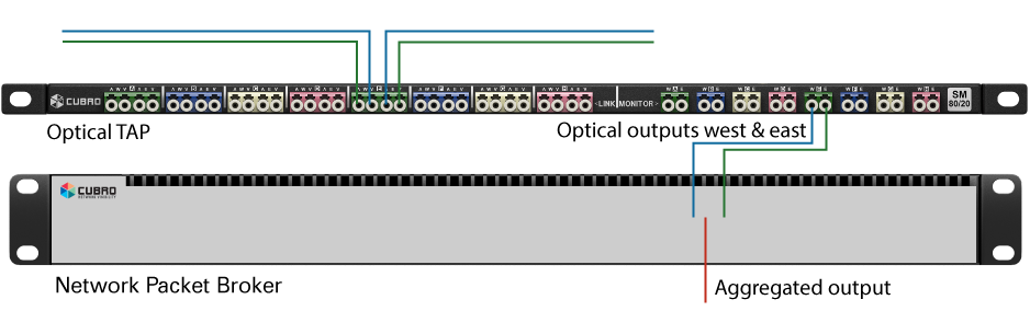
Network Packet Broker is positioned between TAPs and monitoring tools, collects multiple inputs from TAPs, applies aggregation and filtering rules and forwards load-balanced packets to one or multiple monitoring systems.
Simple Use Case Scenario
Problem: A security team needs to monitor application traffic from 1G links but is only interested in HTTP, HTTPS and FTP traffic.
Solution: TAPs are installed on the 1G links and provide packets for the NPB. Some of the switches send packets using spanned ports directly to the NPB.

The packet broker receives the packets from the TAPs and spanned ports, aggregates upstream/downstream streams, filters Layer 4 traffic on TCP ports 80, 443, and 21 and forwards filtered traffic to the IDS/monitoring tool.
Outcome: Reduced tool load, faster analysis, focused visibility.
The NPB in this example is the smallest model of the NPB family, but the principle is the same also for models that support higher bandwidth.
Conclusion
Layer 4 aggregation and filtering are vital techniques in the network visibility stack. Combined with TAPs and packet brokers, they enable organisations to capture the right traffic, at the right time, for the right tools, without dropping packets. As networks become increasingly complex, these functions play a vital role in maintaining control and performance.
Additional Pages & Resources


Looking for support?
Get in touch with our team now
Our newsletter provides thought leadership content about the industry. It is concise and has interesting content to keep you updated with what’s new at Cubro and in the industry. You can unsubscribe anytime with a single click.
Your e-mail address is only used to send you our newsletter and information about the activities of Cubro Network Visibility. You can always use the unsubscribe link included in the newsletter.