


What is a Network TAP?
Content Guide
- Successful 100G & 400G TAP Delivery: Overcoming Connectivity Challenges
- What is the primary function of a network tap?
- Single Mode vs. Multi Mode
- 100G Ethernet Standards
- 400G Ethernet Standards
- Key Takeaways for Matching Network TAPs with Ethernet Standards
- Additional Resources
- FAQs 100G & 400G Network Visibility
Successful 100G & 400G TAP Delivery: Overcoming Connectivity Challenges
The rapid transition from 100G to 400G Ethernet has introduced significant complexities in network monitoring and data acquisition. While 100G TAP deployments are often viewed as standard, critical caveats in fibre and transceiver standards frequently lead to costly connectivity failures.
As 400G network architecture becomes the new benchmark for data centres, understanding 100G/400G interoperability and the physical layer requirements is vital. Eliminating these blind spots requires a deep understanding of Layer 1 to ensure a robust and scalable network visibility foundation.
What is the primary function of a network tap?
Visibility tools and monitoring platforms are only as good as the data they receive. Only TAPs (Test Access Points) guarantee 100% view of the network traffic, providing accurate, complete, and unmodified data.
SPAN (Switched Port Analyser), or a mirror port, is a port on a network switch configured to copy traffic from one or more source ports to a destination port for monitoring.
A mirror session copies the traffic to a SPAN Port. Mirror Session needs to be configured, for example, the following needs to be defined: ingress and/or egress traffic, source port(s) and destination port. If all the traffic needs to be mirrored, then 50% of the ports need to be defined as SPAN ports.
SPAN summary
| Cost | SPAN is a solution built into most network switches, which makes it a cost-effective option for monitoring network traffic. |
| Limitations | Limited number of SPAN ports/mirror sessions, which can introduce costs if an additional switch is needed. Active sessions use hardware resources, risking packet loss and blind spots. May introduce latency. |
| Challenges | Requires expert knowledge for configuration. An incorrect setup can impact the production network or result in blind spots or duplicated data. |
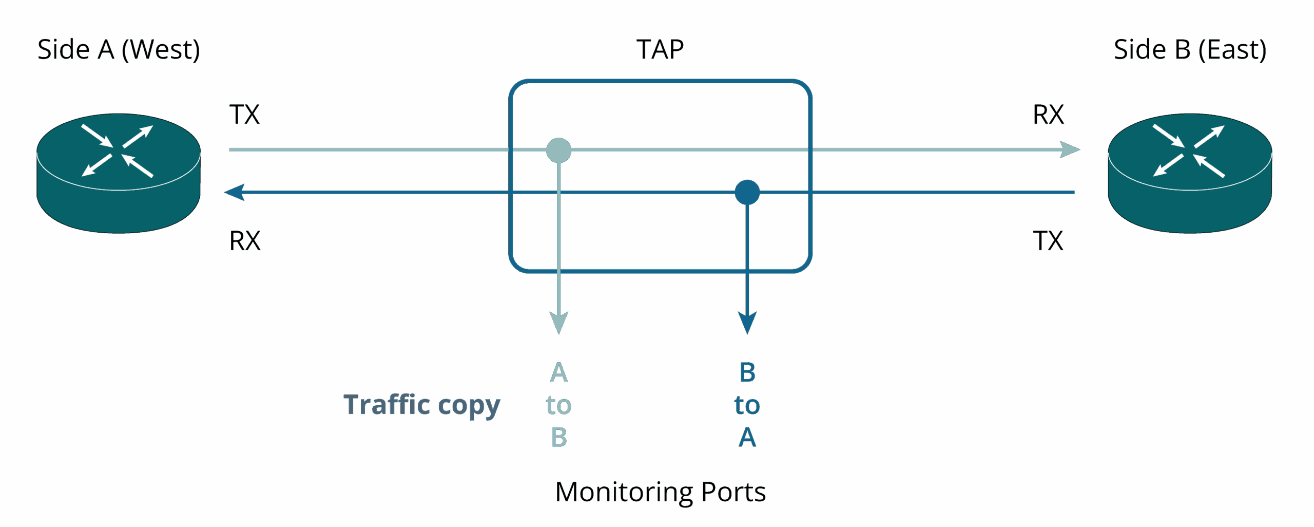
A network TAP has a different principle. It is a hardware device that copies data as it flows through a network cable/link. A link is a pair of TX (transmit) and RX (receive) – also called a full duplex connection. Network TAP sits in-line between two network devices and delivers a 1:1 copy of the traffic running on this link.
Network TAP summary
| Cost | Requires additional hardware and installation |
| Strengths | Transparency: Provides a 1:1 copy of network traffic, including errored packets Passive Operation: Operates externally without affecting network switches. Optical TAP doesn’t use electrical power Flexibility: Compatible with switches, routers, and firewalls Ease of Use: Plug-and-play device, no configuration needed Isolation: Functions as a data diode, ensuring separation between production network and monitoring networks. |
Single Mode vs. Multi Mode
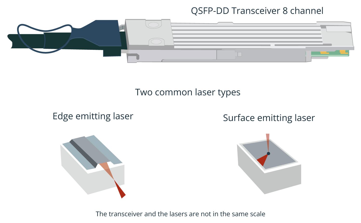
Servers, switches and network equipment are electrical devices. Transceivers are connected to the front-end of these devices and convert electrical to optical signals, and vice versa, using lasers and light detectors built into the transceivers. There are two common types of lasers, one is edge-emitting, and the other is surface-emitting.
Optical TAP is connected to the network links and receives packets from the fibre links. The cables are either SM (Single Mode) or MM (Multi Mode). Depending on the transmission standard used, 100G over Single Mode can be carried over 1 or 4 different wavelengths, whereas Multi Mode is usually transported over 4 independent physical media, each one carrying 25G. Naturally, the transceivers are not the same for SM and MM as the signal processing is different.


The cables end with connectors. The two main types are LC and MTP/MPO. LC is on the left in the next drawing.
The selection of the TAP depends on the connector type, either LC or MTP/MPO. In the following example, MTP/MPO TAP is used. The cable pair from live traffic West, is plugged on the left side of the connector marked as A and live traffic from East to the right side. On the TAP’s monitoring side, the traffic from the West is on the left side and traffic from the East is on the right-hand side, similarly marked as connector A.

100G Ethernet Standards
SM or MM fibres are just the fibre type; interoperability requires that the same matching standard is used. Standard defines the wavelength, modulation, whether multiplexing is used or not and the connector type.
100G SR4
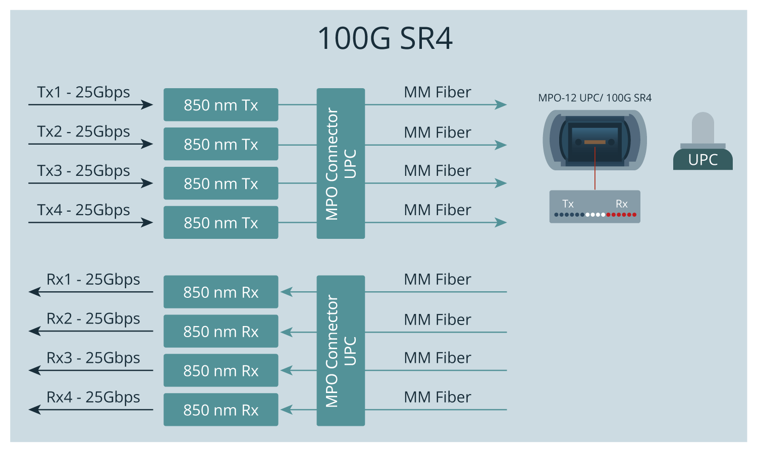
For 40G and 100G over Multi Mode the Ethernet standard is called SR4 (short reach, 4 lane). It uses 4 independent fibres for sending and 4 fibres for receiving data at 850 nm wavelength. For 40G each lane carries 10G, whereas 100G has 4 lanes of 25G. The reach of MM with SR4 is 100m or less. 100G SR4 uses MPO-12 connector with UPC (Ultra Physical Contact).
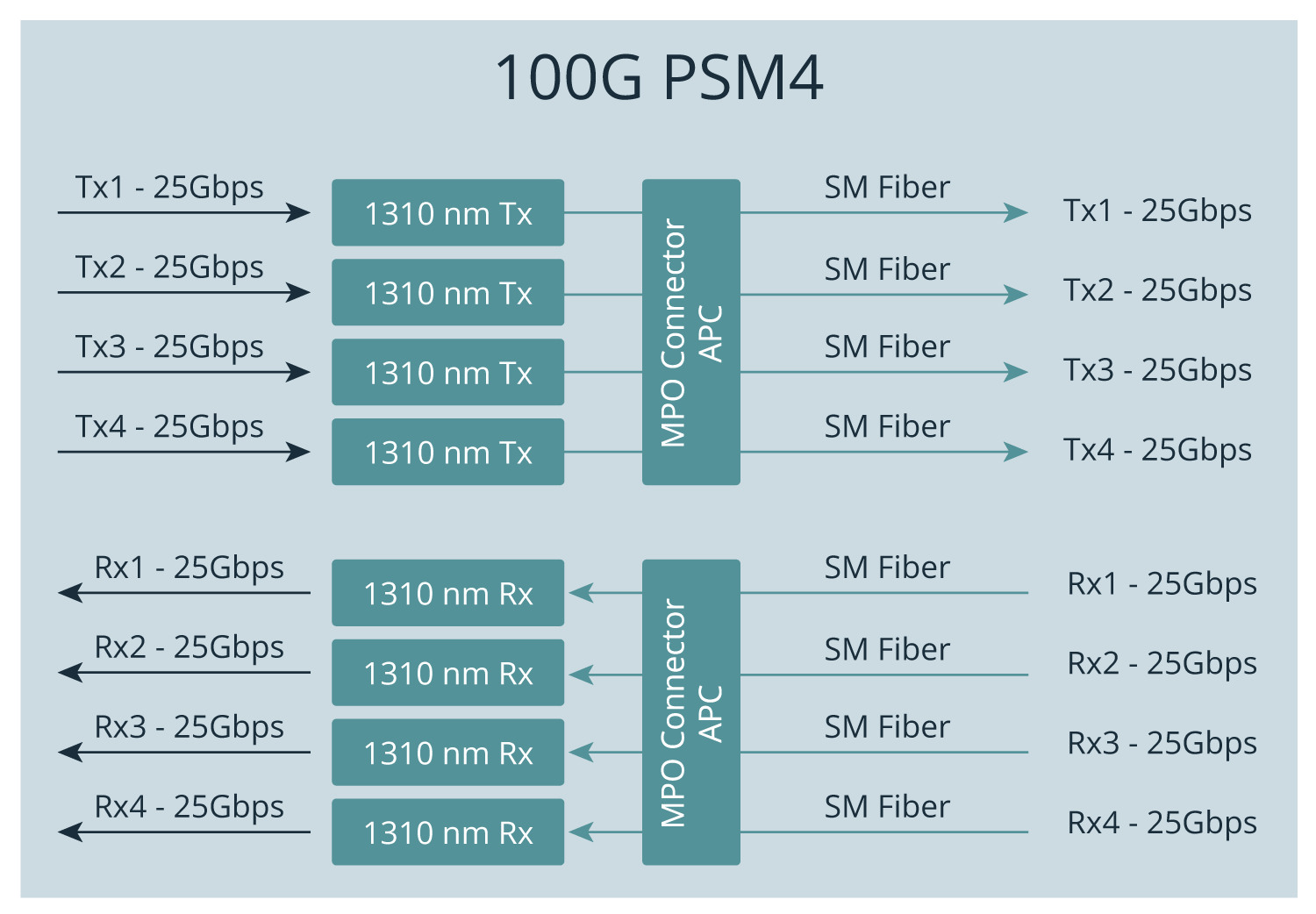
100G PSM4
An Ethernet standard for Single Mode that is similar to MM SR4 is called PSM4 (Parallel Single-Mode 4 channel). It also uses individual fibres, but the wavelength is 1310 nm, and the connector type is MPO / APC. PSM4 reach is 1 km under ideal conditions.
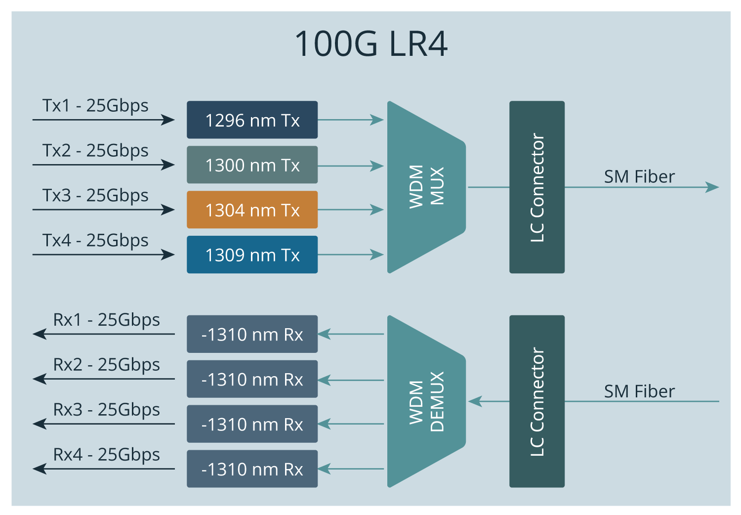
100G LR4
SM has several other standards.
For 40G and 100G single-mode applications, the highest-reach option is LR4 (Long Range, 4 channels). It uses duplex fibre – one fibre for transmitting (Tx) and one for receiving (Rx). (long range, 4 channel). It uses 1 fibre for sending and 1 fibre for receiving data. A WDM multiplexer combines the wavelengths at 1296, 1300, 1304, and 1309 nm into a single signal.
On the receiving end, the signal is received by the WDM de-multiplexer and divided into 4 channels. The benefit of using SM with this standard is its long reach, which can be up to 10km.
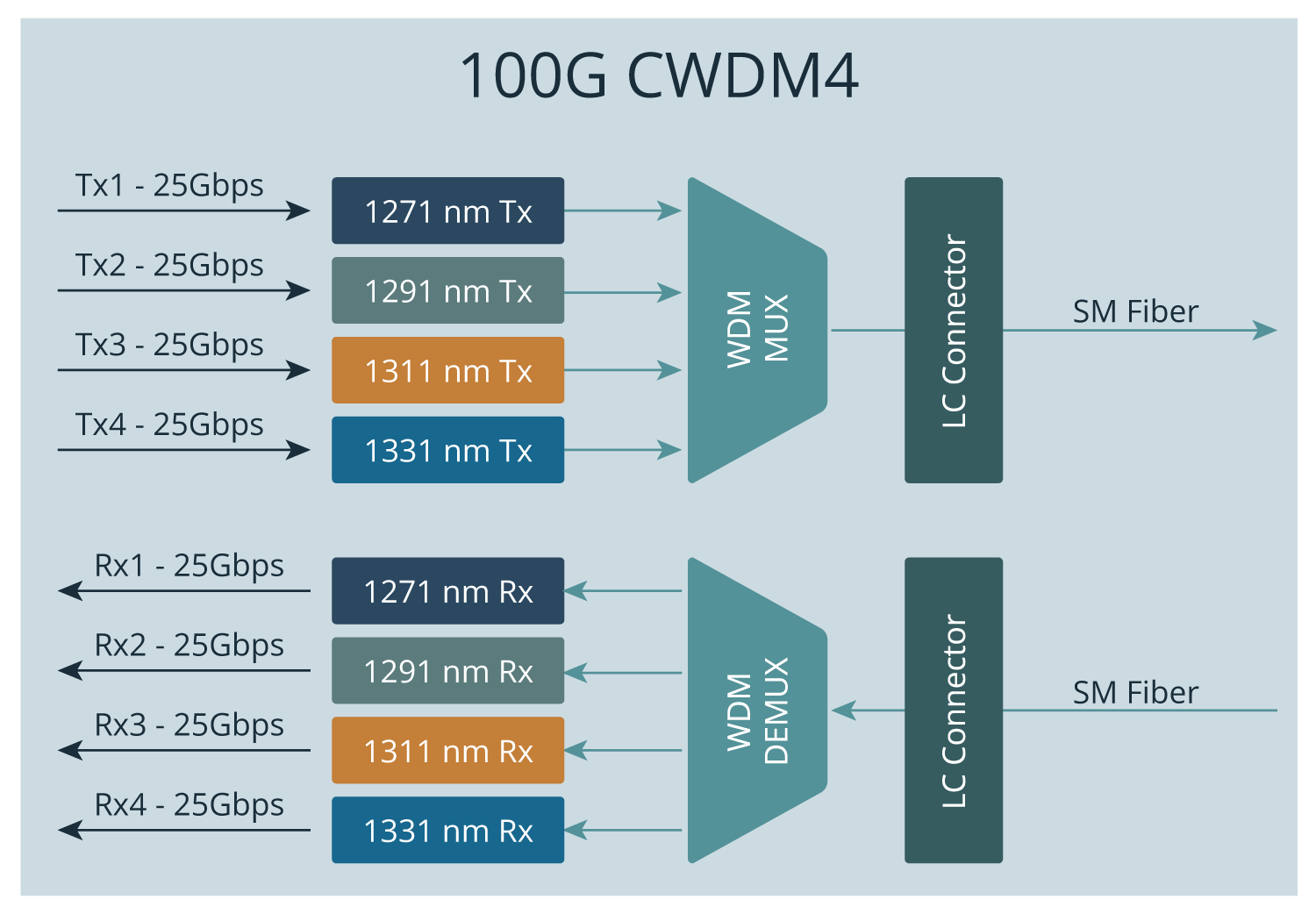
100G CWDM4
Yet another standard for SM is CWDM4 (Coarse Wavelength Division Multiplexing 4). It has a slightly higher reach than PSM4, but lower than LR4, reaching up to 2 km. Due to the 20nm wavelength difference in the channels the transceivers are cheaper to produce compared to LR4.
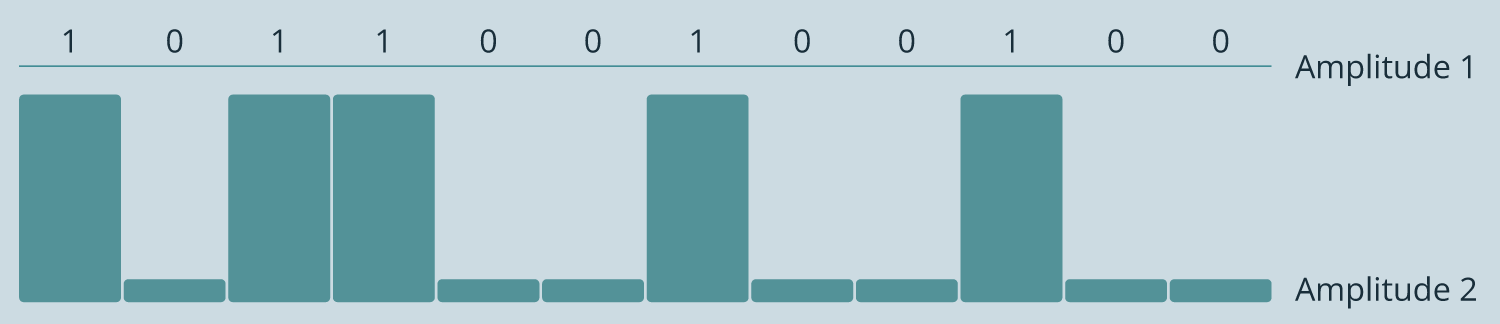
Compatibility requires that the used standard is the same on both ends. For example, CWDM4 will not work with LR4 because they use different wavelengths, and it will not work with PSM4 because PSM4 uses 4 fiber pairs. SR4, LR4, PSM4 and CWDM4 all use NRZ (non-return -to-zero) line code, where a higher voltage represents 1 and a lower voltage represents zero. NRZ makes the electrical and line rates the same. This concept is important once we look at 400G standards.
400G Ethernet Standards
There are three 400G standards for MM: 400GBASE-SR16, 400GBASE-SR8 and 400GBASE-SR4.2. SM has even more: 400GBASE-DR4, 400GBASE-FR8, 400GBASE-LR8, 400GBASE-ER8, 400GBASE-ZR, 400GBASE-FR4, 400GBASE-LR4, 400GBASE-CWDM8-2 and 400GBASE-CWDM8-10.
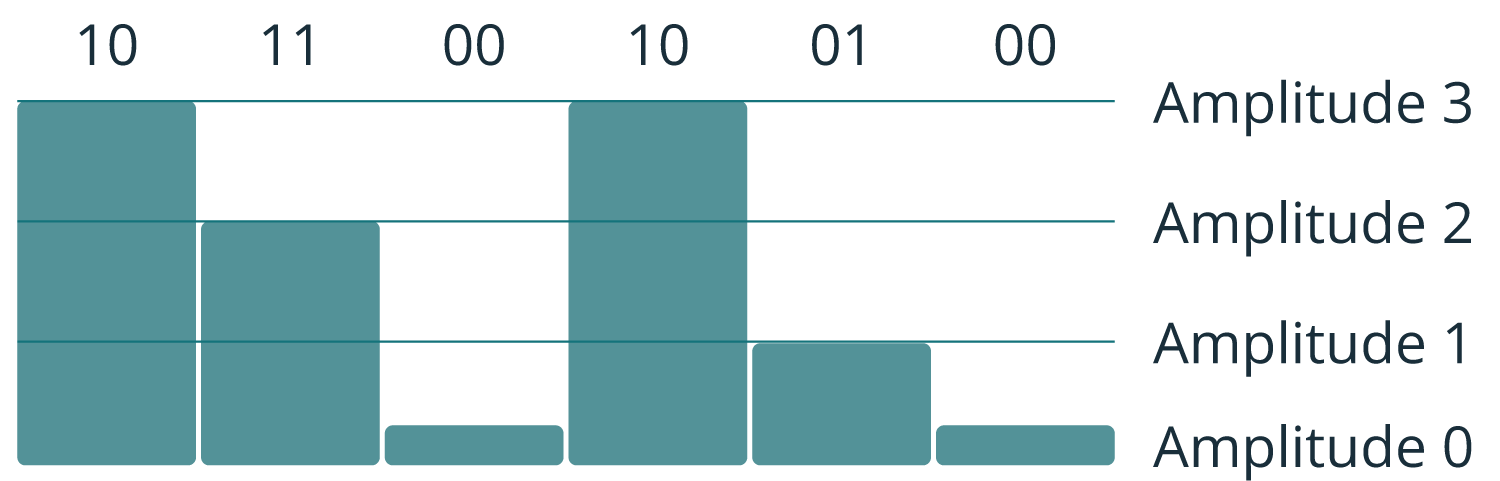
400G uses PAM4 (Pulse Amplitude Modulation 4) instead of NRZ. NRZ has two levels, either zero or one, in other words one symbol carries one bit. PAM4 has four levels, each level (symbol) representing 2 bits. This means more efficiency, because PAM4 encoding can carry twice the information compared to NRZ.
400G SR8
There are some drawbacks. Reduced SNR (Signal-Noise Ratio) puts higher requirements for links in terms of clock stability and receiver quality. For 100G FEC (Forward Error Correction) is optional, but with 400G, it is mandatory.
The 400G SR8 looks similar to the 100G SR4 standard, but a total of 8+8 fibres are used with the MPO-16 APC connector.
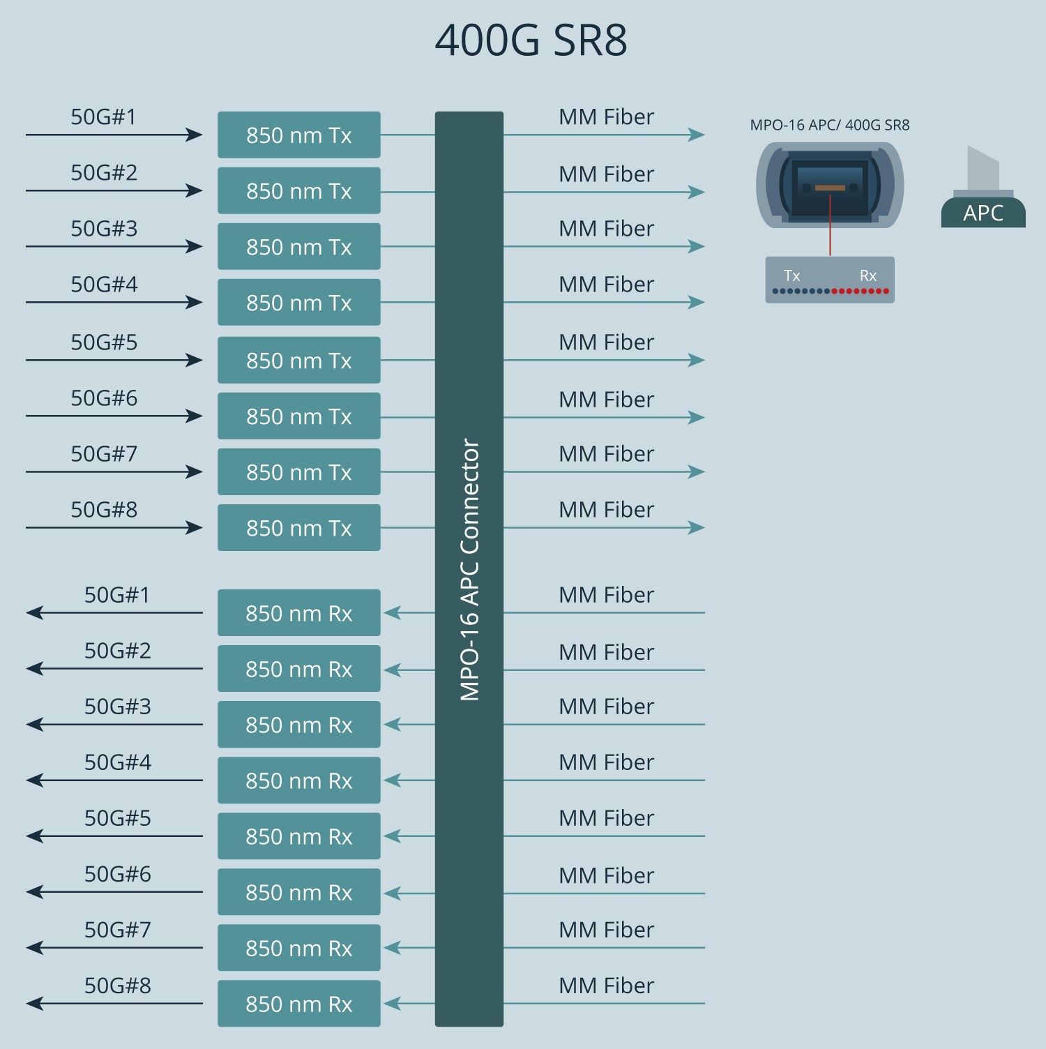
16 fibres require a TAP device that supports them.

400G DR4, XDR4, PLR4

In the 400G ecosystem, DR4, XDR4, and PLR4 rely on an MPO-12 APC connector with 8 fibres, following the same approach as 100G PSM4.
The TAP used for this standard supports 40G, 100G, and 400G interfaces based on multi-fibre transmission with MPO APC, SM, and 1310nm, such as 40G or 100G PSM4 and 400G DR4/XDR4/PLR4.
The 400G FR4 and LR4 standards define the next category of single-mode optical interfaces.
400G FR4, LR4
400G FR4 and LR4 use wavelength multiplexing to a Single Mode fibre which is exactly as used for 100G LR4. Thus, tapping also follows the same principle, and the TAP device that works for 100G LR4 can also be used for 400G FR4 and 400G LR4. Moreover, the same TAP can also be used for 1G LR and 10G LR.


Key Takeaways for Matching Network TAPs with Ethernet Standards
For any tapping application, the underlying principle of transmission needs to be understood. TAP needs to be selected based on the Ethernet Standard used. A bit exaggerated example: A TAP that works for 1G over Multi Mode fibre (=1G SR standard) cannot be used for 100G SR4 or 400G SR8, because it uses completely different technology. Furthermore, 400G requires even more attention; 400G introduces new Ethernet standards that are sometimes not compatible with older ones.
Additional Resources


How to Build a Robust Network Visibility Foundation with Network TAPs-Webinar Recording
FAQs 100G & 400G Network Visibility
The primary difference lies in the modulation. 100G typically uses NRZ (Non-Return-to-Zero) signalling, where one symbol carries one bit. 400G utilises PAM4 (Pulse Amplitude Modulation 4-level), which carries two bits per symbol. While PAM4 is more efficient, it significantly reduces the Signal-to-Noise Ratio (SNR), making Forward Error Correction (FEC) mandatory for 400G.
At high speeds, SPAN (mirror) ports often become a bottleneck. They consume switch hardware resources, which can lead to packet loss and increased latency. Furthermore, SPAN ports often filter out errored packets. Only a passive network TAP guarantees a 1:1 copy of all traffic, including physical layer errors, without impacting production network performance.
It depends on the standard. A 100G PSM4 TAP may be compatible with 400G DR4, XDR4, and PLR4 interfaces because they both utilise MPO-12 APC connectors and 8-fiber Single-Mode transmission. However, standards like 400G SR8 require an MPO-16 connector and 16 fibres, which are incompatible with standard 100G hardware.
- SR4 (Short Reach): Multi-mode fibre, uses 8 fibres (4 TX/4 RX) via MPO-12/UPC connectors.
- LR4 (Long Range): Single-mode fibre, uses WDM to multiplex 4 wavelengths over a single fibre pair via LC connectors (up to 10km).
- CWDM4: Similar to LR4 but optimised for shorter distances (up to 2km), making the transceivers more cost-effective. It is not compatible with LR4.
The TAP must match the physical cabling of the live link. LC connectors are typically used for multi-wavelength signals (like LR4), while MPO/MTP connectors are used for parallel fibre signals (like SR4 or PSM4). Selecting the wrong connector type or the wrong endface (APC vs. UPC) will prevent the link from establishing a connection.
No. A passive optical TAP operates without electrical power. It uses a splitter to physically “split” the light signal, ensuring the TAP remains a “data diode” that cannot be hacked and will not fail even if the monitoring tool loses power.
Our newsletter provides thought leadership content about the industry. It is concise and has interesting content to keep you updated with what’s new at Cubro and in the industry. You can unsubscribe anytime with a single click.
Your e-mail address is only used to send you our newsletter and information about the activities of Cubro Network Visibility. You can always use the unsubscribe link included in the newsletter.